TMS 602 Article 1.6E (Grout Demonstration Panel) requires a grout demonstration panel if the applicable requirements of Article 3.5C (Grout Pour Height), Article 3.5D (Grout Lift Height), and 3.5E (Consolidation) are not met. According to TMS 602 Article 3.5G, alternate grout procedures (those that differ from TMS 602 Articles 3.5C, 3.5D, and 3.5E) may be employed when the grout demonstration panel is accepted by the Architect/Engineer. The requirements for cleanouts are given in TMS 602 Article 3.2F and are, therefore, independent of the requirements that may be waived through an accepted grout demonstration panel.
Consequently, a grout demonstration panel cannot be relied upon by the Architect/Engineer to eliminate the need for cleanouts when the grout pour heights exceed 5’-4”. The only recourse for a contractor who wants to avoid cleanouts and still construct masonry to a pour height that exceeds 5’-4” is to obtain approval of the building official for a “special system of construction”, as permitted by TMS 402 Section 1.3 (Alternative design or method of construction) or IBC Section 104.11 (Alternative materials, design and methods of construction and equipment).
Resources
Society, The Masonry (2016). TMS 402/602 Building Code Requirements and Specification for Masonry Structures, 2016. The Masonry Society.
Society, The Masonry (2013). TMS 402/602 Building Code Requirements and Specification for Masonry Structures, 2013. The Masonry Society.
International Code Council (2018). International Building Code, 2018. International Code Council.
International Code Council (2015). International Building Code, 2015. International Code Council.
The masonry code and specification referenced by IBC 2018 is the TMS 402/602-16 Building Code Requirements and Specification for Masonry Structures. TMS 602 Specification, Article 3.5 D. addresses grout lift heights.
There are basically four types of grouting (see Table 1):
- Grouting with no cure time limit
- Conventional grout with no intermediate bond beams
- Conventional grout with intermediate bond beams
- Self-consolidating grout with or without intermediate bond beams.
There are two terms that need to be defined: “grout lift” and “grout pour”.
- Grout pour is the total height of masonry to be grouted prior to erection of additional masonry. A grout pour consists of one or more grout lifts.
- Grout lift is an increment of grout height within a total grout pour. A grout pour consists of one or more grout lifts.
Resources:
TMS 402/602-16 Building Code Requirements and Specification for Masonry Structures
As it relates to specifying grout for masonry, the MIM recommends the following:
- Grout shall be specified in conformance with ASTM C476. Conventional grout should be specified by proportions instead of by strength requirements.
- The minimum specified compressive strength of grout (f’g) shall be 2,000 psi (13.79 MPa), unless the structural design assumptions require a higher specified compressive strength of clay masonry or concrete masonry (f’m). In that case, the grout compressive strength shall equal or exceed f’m. Compressive strength shall be tested in accordance with ASTM C1019, when required.
- Fine or coarse grout are permitted, though the MIM recommends specifying coarse unless there is a known issue with grout space or clear cover due to reinforcement congestion or unit size. Coarse grout is the most common in the Michigan market and is generally less expensive on a unit basis.
- If conventional grout is specified by proportions, which the MIM recommends, then compressive strength testing of grout specimens is not required during construction unless the design requires an f’m greater than 2,000 psi (13.79 MPa), as noted in TMS Article 2.2 B. TMS 602 Table 4, Minimum Special Inspections, requires periodic verification of the proportions of site-prepared grout for Level 2 and Level 3 Quality Assurance.
TMS 402 (2016) Requirements
TMS 402 Section 6.1.3.5 states that, “Reinforcement embedded in grout shall have a thickness of grout shall have thickness of grout between the reinforcement and masonry units of not less than 1/4 in. (6.4 mm) for fine grout of 1/2 in. (12.7 mm) for coarse grout.”
For Strength Design of Masonry, TMS 402 Section 9.1.9.1.2 Grout compressive strength states, “For concrete masonry, the specified compressive strength of grout, f’g, shall equal or exceed the specified compressive strength of masonry, f’m, but shall not exceed 5,000 psi (34.47MPa). For clay masonry the specified compressive strength of grout, f’g, shall not exceed 6,000 psi (41.37 MPa).”
In the 2022 edition of TMS 402, the grout compressive strength requirements were moved to Section 4.3, and thus apply to masonry designed under both the Allowable Stress Design and Strength Design methodologies. The grout compressive strength requirements are located in Table 4.3.1 of the TMS 402 (2022).
TMS 602 (2016) Requirements
TMS 602 Article 1.5 B states that the following must be submitted for each grout mix:
- Mix designs indicating type and proportions of the ingredients according to the proportion requirements of ASTM C476, or
- Mix designs and grout strength test performed in accordance with ASTM C476, or
- Compressive strength tests performed in accordance with ASTM C1019, and slump flow and Visual Stability Index (VSI) as determined by ASTM C1611/C1611M.
TMS 602 Article 1.6A Testing Agency’s services and duties and Table 4 – Minimum Special Inspection Requirements require that, as masonry construction begins, periodic verification of the proportions of site-prepared grout is required for Level 2 and Level 3 Quality Assurance.
TMS 602 Article 2.2 Grout Materials states,
2.2 A. Unless otherwise required, provide grout that conforms to the requirements of ASTM C476.
2.2 B. When f’m exceeds 2,000 psi (13.79 MPa), provide grout compressive strength that equals or exceeds f’m. Determine compressive strength of grout in accordance with ASTM C1019.
2.2 C. Do not use admixtures unless acceptable. Field addition of admixtures is not permitted in self-consolidating grout.
TMS 602 Article 3.5 C Grout pour height states, “Do not exceed the maximum grout pour height given in Table 6.”
Table 6 – Grout space requirements
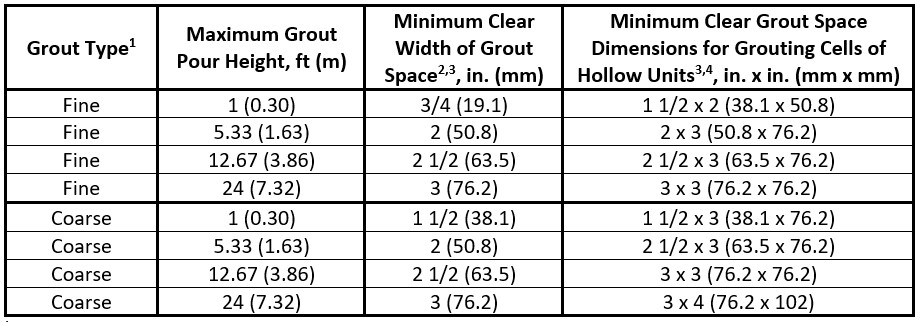
1 Fine and coarse grouts are defined in ASTM C476
2 For grouting between masonry wythes
3 Minimum clear width of grout space and minimum clear grout space dimensions are the net dimension of the space determined by subtracting masonry protrusions and the diameters of horizontal bars from the as-built cross section of the grout space. Select the grout type and maximum grout pour height based on the minimum clear space.
4 Minimum grout space dimension for AAC masonry units shall be 3 in. (76.2 mm) x 3 in. (76.2 mm) or a 3 in. (76.2 mm) diameter cell.
As noted in Footnotes 2 and 3, the minimum width of grout space is used when the grout is placed in collar joints, where the minimum cell dimensions are used when grouting cells of hollow masonry units, including consideration of vertical alignment of the cells. The grout space dimensions are smallest clear dimensions, considering projections or obstructions into the grout space and the diameter of horizontal reinforcement. This is illustrated in TMS 402 (2016) Figure CC-3.2.1, which has been copied below for reference:
![]()
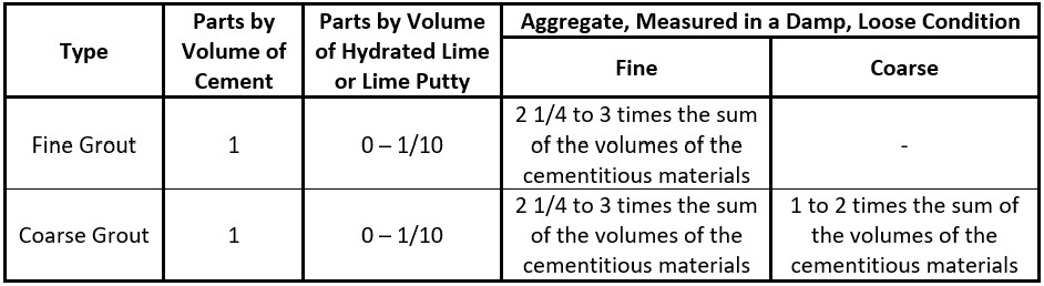
ASTM C476 Requirements
ASTM C476 covers two types of grout, fine and coarse grout, for use in the construction of masonry structures. Conventional grout is specified by (1) proportions or (2) strength requirements.
Section 4 Grout Type and Proportions states:
4.1 Type – Grout type shall be specified as fine or coarse.
4.1.1 Fine grout shall be manufactured with fine aggregates.
4.1.2 Coarse grout shall be manufactured with a combination of coarse and fine aggregates.
Note: Building code provisions and grout space dimensions should be reviewed when selecting grout type or types.
4.2 Proportions of Ingredients – Proportions shall be determined as follows:
4.2.1 Conventional Grout – Proportions shall be determined by one of the following methods:
4.2.1.1 Requirements of Table 1.
4.2.1.2 Specified Compressive Strength – Proportions established by 28-day compressive strength tests in accordance with Test Method C1019 that equal or exceed the specified compressive strength. The grout shall be mixed to a slump of 8 to 11 in. (200 to 280 mm) as determined by Test Method C143/C143M and shall have a minimum compressive strength of 2000 psi (14 MPa) at 28 days.
Table 1 Conventional Grout Proportions by Volume
Resources:
Society, The Masonry (2016). TMS 402/602 Building Code Requirements and Specification for Masonry Structures, 2016. The Masonry Society.
ASTM Standard C476, “Standard Specification for Grout for Masonry,” ASTM International, West Conshohocken, PA, 2020.
Steel reinforcement in masonry is protected from corrosion by one or more construction practices; cover by cementitious materials (mortar or grout) and/or by application of a corrosion-resistant coating. The protective coating can be mill galvanizing, hot-dip galvanizing, epoxy, or, alternatively, use of stainless steel instead of carbon steel. Steel joint reinforcement is required by TMS 402/602 to be protected by both construction practices (cover and coating). The type and thickness of corrosion-resistant coating depends on whether the masonry is exposed to weather or high humidity (such as in natatoria).
Although TMS 402/602 permits steel reinforcing bars to be galvanized or epoxy-coated, TMS 402/602 does not require a corrosion-resistance protective coating. This is because the depth of masonry cover (combination of grout, mortar, and masonry units) is much larger than the mortar cover over joint reinforcement. Masonry cover over steel reinforcing bars provides sufficient corrosion protection without the need for a protective coating.
According to NCMA TEK 12-4D, “A minimum amount of masonry cover over reinforcing bars is required to protect against steel corrosion…These requirements also help minimize corrosion by providing for a minimum amount of masonry and grout cover around reinforcing bars…”
The other reason why corrosion-resistant coatings are not required and are not commonly used on masonry reinforcement is because masonry is primarily constructed in vertical planes. Conversely, concrete slabs-on-grade, where deicing salts are routinely applied, are subject to chloride intrusion and accelerated corrosion of embedded steel. Steel reinforcement in these members is routinely protected by a corrosion-resistant coating, in addition to being placed with a larger amount of concrete cover. Masonry is not typically exposed to salts in this way.
Epoxy coating is another protective coating that is commonly used in concrete members that are exposed to deicing salts. Although epoxy coating is also permitted by TMS 402/602, bars with epoxy coating are required to have a longer lap length than those without that coating due to the reduced bond development. Epoxy coating results in additional cost and difficulty in construction, which are not justified by substantive improvement in masonry performance because masonry is not exposed to conditions that would warrant that level of protection.
Resources:
National Concrete Masonry Association. (2006). TEK 12-04D Steel Reinforcement for Concrete Masonry. https://ncma.org/resource/steel-reinforcement-for-concrete-masonry/
Society, The Masonry (2016). TMS 402/602 Building Code Requirements and Specification for Masonry Structures, 2016. The Masonry Society.
Society, The Masonry (2013). TMS 402/602 Building Code Requirements and Specification for Masonry Structures, 2013. The Masonry Society.
The tolerance for mortar bed joint thickness specified in the TMS 602 is plus or minus 1/8-inch from the specified dimension. In standard modular construction, the default specified bed joint thickness is 3/8-inch. Therefore, a standard mortar bed joint can be placed with a minimum 1/4-inch thickness.
Placing 3/16-inch joint reinforcement wire on the top surface of the concrete masonry units (CMUs) would, theoretically, leave 1/16-inch of top mortar coverage above the wire. However, no top mortar coverage may result when construction tolerances and TMS 402/602 corrosion protection for the joint reinforcement are considered as follows:
- Two (2) or three (3) mil thickness of galvanizing increases the wire diameter by four (4) to six (6) mils.
- The as-manufactured top and bottom surfaces of a CMU can vary due to texture.
- The top surface of CMU courses is required by TMS 602 to be placed true-to-a-line, but the permitted tolerance for true-to-a-line is plus or minus 1/4-inch in 10-feet.
- The height of individual CMUs can vary by plus or minus 1/8-inch (per ASTM C90) from the specified height, resulting in potential offsets in the bottom of the CMU course above the joint reinforcement.
- A 10-foot length of horizontal joint reinforcement will have some curvature.
Heavy duty (3/16-inch) joint reinforcement can, theoretically, be placed in a 3/8-inch joint. However, limiting such heavy duty joint reinforcement to construction in which the specified mortar bed joint thickness is 1/2-inch or more should be considered to accommodate the tolerances described above.
According to Selecting the Right Joint Reinforcement for the Job, “One compelling reason to use 9 gauge joint reinforcement is for fit and constructability. While the code allows joint reinforcement to have a diameter one half the mortar joint width, the tolerances allowed for units, joints, and the wire itself can hinder the placement of large diameter reinforcement. Use it only when there is no other choice.”
Resources:
Society, The Masonry (2016). TMS 402/602 Building Code Requirements and Specification for Masonry Structures, 2016. The Masonry Society.
Society, The Masonry (2013). TMS 402/602 Building Code Requirements and Specification for Masonry Structures, 2013. The Masonry Society.
Joint Reinforcement: Less is More. (July 2015). Masonry Magazine, 44-50.
https://www.masonrymagazine.com/blog/2015/06/24/joint-reinforcement-less-is-more/
Selecting Joint Reinforcement. (June 2014). The Construction Specifier Magazine, 50-58.
https://www.constructionspecifier.com/selecting-joint-reinforcement/
Selecting the Right Joint Reinforcement for the Job. (January 1995). Masonry Construction Magazine, 8-14.
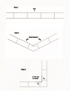
Yes, straight lengths of horizontal joint reinforcement can be field-fabricated to form a continuous corner as follows:
- Cut one longitudinal wire,
- Bend the other longitudinal wire to for a 90-degree angle,
- Bend the cut ends of the longitudinal wire 90-degrees to lap the other cut sections of the longitudinal wire to form the required minimum 6-inch lap splice.
The figure below depicts a 90-degree outside corner of joint reinforcement that has been field fabricated with he required lap splice. The same configuration can be used at an inside corner.
Prefabricated joint reinforcement corners are available from joint reinforcement manufacturers, but field-formed corners have some advantages over prefabricated corners:
- No extra lead time needed for ordering
- No additional cost to purchase
- More likely to be installed because the material is available on the project site
- Can be custom cut to length and lapped per course, when building a corner lead (racking back)
The TMS 602 does not include a requirement for continuity of horizontal joint reinforcement at corners and, therefore, does not address how to achieve continuity at corners. Nevertheless, constructing joint reinforcement with continuity at corners is good practice and reduces the potential for shrinkage cracking at wall corners.
According to Dr. Thomas J. Langill, Technical Director, American Galvanizers Association, susceptibility to corrosion at the bend, due to potential damage to the zinc galvanizing, is not a concern. “In the case of bending the wire the usual thickness of galvanized coating on the wire makes the potential of coating cracking or crazing during bending very low. Even small cracks in the coating t the bend will not affect the corrosion performance.”
Resources:
Joint Reinforcement: Less is More. (July 2015). Masonry Magazine, 44-50.
https://www.masonrymagazine.com/blog/2015/06/24/joint-reinforcement-less-is-more/
Selecting Joint Reinforcement. (June 2014). The Construction Specifier Magazine, 50-58.
https://www.constructionspecifier.com/selecting-joint-reinforcement/
Society, The Masonry (2016). TMS 402/602 Building Code Requirements and Specification for Masonry Structures, 2016. The Masonry Society.
Society, The Masonry (2013). TMS 402/602 Building Code Requirements and Specification for Masonry Structures, 2013. The Masonry Society.
No, neither the TMS 402/602 nor the Michigan Building Code require rebar positioners.
The Michigan Building Code references the TMS 402/602. Neither the TMS 402 nor the TMS 602 require rebar positioners or tying of reinforcing bars.
The commentary to TMS 402 Section 6.1.3 states, “Reinforcing bar positioners are available to control bar position.” However, the corresponding Code section does not require use of such positioners. Figure SC-11 in TMS 602 illustrates typical reinforcing bar positioners, but Article 3.4.B.1 merely states, “Support reinforcement to prevent displacement caused by construction loads or by placement of grout or mortar, beyond the allowable tolerances” without requiring use of positioners. The TMS Masonry Designers Guide (MDG), which is prepared to help users apply the provisions of TMS 402/602, confirms this. In Section 4.2.2.3 (Reinforcing Bars), MDG states, “However, TMS 602 does not require the use of positioners, nor does it specify a maximum spacing for them.”
Although reinforcing bars are not prohibited from being tied, neither the TMS 402 nor the TMS 602 require tying of reinforcement. In fact, both the TMS 402 and the TMS 602 specifically permit reinforcing bars to be lap spliced while not in contact. The MIA Inspector’s Handbook, which was developed as a guide for reinforced hollow unit concrete masonry construction, states in Section 5.7 (Lap Splices, Reinforcing Bars), “Physical tying, or contact, is not a requirement for transferring stresses, however, a designer may require tying of reinforcing bars in the project specifications.”
Resources:
Society, The Masonry (2016). TMS 402/602 Building Code Requirements and Specification for Masonry Structures, 2016. The Masonry Society.
Society, The Masonry (2013). TMS 402/602 Building Code Requirements and Specification for Masonry Structures, 2013. The Masonry Society.
International Code Council (2018). International Building Code, 2018. International Code Council.
International Code Council (2015). International Building Code, 2015. International Code Council.
Society, The Masonry. (2016). The Masonry Society’s Masonry Designers’ Guide, 2016. The Masonry Society.
Masonry Institute of America (2015). Reinforced Concrete Masonry Construction Inspector’s Handbook, 9th Edition. Masonry Institute of America.
Chapter 6 of the TMS 402 (Reinforcement, Metal Accessories, and Anchor Bolts) contains general requirements for reinforcement used in masonry. Specifically, Chapter 6 contains the following requirements:
- Section 6.1.2.1 limits the maximum size of reinforcement to a No. 11 bar.
- Section 6.1.2.2 limits the diameter of reinforcement bars to not more than one-half of the least clear dimension of the cell, bond beam or collar joint in which it is placed.
- Section 6.1.2.4 states that the area of vertical reinforcement shall not exceed 6 percent of the area of the grout space.
- Note: The draft 2022 TMS 402 document reduces this permitted area to 4 percent of the grout space but this is not yet finalized.
- Note: The TMS 402 Code and Commentary do not include any language relative to locations containing lap splices.
- Section 6.1.2.5 states that the nominal bar diameter shall not exceed one-eighth of the least nominal member dimension (e.g., the maximum size of reinforcement in an 8-inch CMU would be a #8 bar based on Section 6.1.2.5).
These limits would apply to all masonry construction regardless of design methodology. Beyond these general requirements, the TMS 402 includes restrictions on the placement of reinforcement as follows:
- Section 6.1.3.1 states that the clear distance between parallel bars shall not be less than the nominal diameter of the bars, nor less than 1 in. (e.g., for bar sizes less than or equal to a No. 8, a 1 in. minimum clear distance is required between parallel bars).
- Section 6.1.3.5 states that reinforcement embedded in grout shall have a thickness of grout between the reinforcement and masonry units not less than 1/4 in. for fine grout or 1/2 in. for coarse grout.
- Section 6.1.4.1 states that reinforcing bars shall have a masonry cover not less than the following:
- Masonry exposed to earth or weather: 2 in. for bars larger than No. 5; 1 1/2 in. for No. 5 bars or smaller.
- Masonry not exposed to earth or weather: 1 1/2 in.
For the purposes of this FAQ, we will focus on the Allowable Stress Design and Strength Design methodologies. Chapter 8 of the TMS 402 (Allowable Stress Design) does not include any additional limitations beyond those found in Chapter 6 (Reinforcement, Metal Accessories, and Anchor Bolts). Chapter 9 of the TMS 402 (Strength Design) includes additional limitations, many of which are more restrictive, on reinforcement as shown below:
- Section 9.3.1 states that reinforcing bars used in masonry shall not be larger than a No. 9.
- Section 9.3.1 also states that the nominal bar diameter shall not exceed one-quarter of the least clear dimension of the cell, course, or collar joint in which the bar is placed.
- Section 9.3.1 also states that the area of reinforcing bars placed in a cell or in a course of a hollow unit construction shall not exceed 4 percent of the cell area. The TMS 402 commentary recommends that at sections containing lap splices, the maximum area of reinforcement should not exceed 8 percent of the cell area.
Chapter 9 of the TMS 402 (Strength Design) also includes limitations on the maximum area of flexural tensile reinforcement in Section 9.3.3.2. These requirements are outside the scope of this FAQ.
For the purposes of this FAQ, we will focus on five unit types:
- Flanged Concrete Masonry Units (Figure 1)
- Jamb Concrete Masonry Units (Figure 2)
- Open-End Concrete Masonry Units (Figure 3)
- Circular Core Clay Masonry Units (Figure 4)
- Rectangular Core Clay Masonry Units (Figure 5)
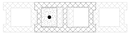
Figure 1: Flanged Units in One-Half Running Bond
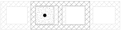
Figure 2: Jamb Units in One-Half Running Bond
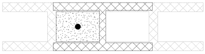
Figure 3: Open-End Units in One-Half Running Bond
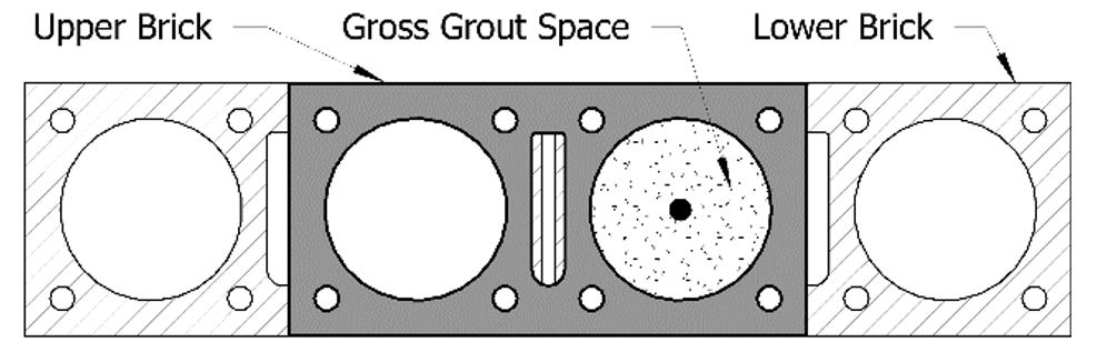
Figure 4: Circular Core Units in One-Half Running Bond
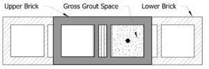
Figure 5: Rectangular Core Units in One-Half Running Bond
TMS 602 Article 3.3 B.2.c requires the mason contractor to remove masonry protrusions extending 1/2 in. or more into cells or cavities to be grouted. Additionally, concrete masonry unit (CMU) molds typically result in a taper of both the face shells and the webs that will restrict cell area. Tables 1 and 2 below are based on conservative mold drawings that MIM had available and the Strength Design provisions presented above and in the TMS 402. Unless specific mold drawings are available from the producer, the engineer may conservatively use these tables to determine the maximum size of reinforcement permitted for various nominal masonry thicknesses.
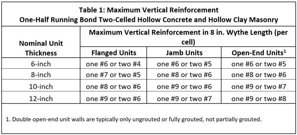
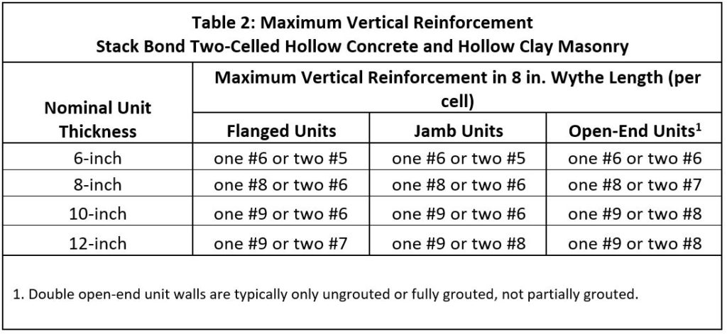
Using the Allowable Stress Design provisions, the 2013 and 2016 versions of the TMS 402 permit a larger area of reinforcement that can be used in hollow concrete and hollow clay masonry units. MIM does not advise using these larger sizes unless specifically required for unique structural situations.
Resources:
Society, The Masonry (2016). TMS 402/602 Building Code Requirements and Specification for Masonry Structures, 2016. The Masonry Society.
Society, The Masonry (2013). TMS 402/602 Building Code Requirements and Specification for Masonry Structures, 2013. The Masonry Society.
Chapter 6 of the TMS 402 (Reinforcement, Metal Accessories, and Anchor Bolts) contains general requirements for reinforcement used in masonry. Specifically, Chapter 6 contains the following requirements:
- Section 6.1.2.1 limits the maximum size of reinforcement to a No. 11 bar.
- Section 6.1.2.2 limits the diameter of reinforcement bars to not more than one-half of the least clear dimension of the cell, bond beam or collar joint in which it is placed.
- Section 6.1.2.4 states that the area of vertical reinforcement shall not exceed 6 percent of the area of the grout space.
- Note: The draft 2022 TMS 402 document reduces this permitted area to 4 percent of the grout space but this is not yet finalized.
- Note: The TMS 402 Code and Commentary do not include any language relative to locations containing lap splices.
- Section 6.1.2.5 states that the nominal bar diameter shall not exceed one-eighth of the least nominal member dimension (e.g., the maximum size of reinforcement in an 8-inch CMU would be a #8 bar based on Section 6.1.2.5).
These limits would apply to all masonry construction regardless of design methodology. Beyond these general requirements, the TMS 402 includes restrictions on the placement of reinforcement as follows:
- Section 6.1.3.1 states that the clear distance between parallel bars shall not be less than the nominal diameter of the bars, nor less than 1 in. (e.g., for bar sizes less than or equal to a No. 8, a 1 in. minimum clear distance is required between parallel bars).
- Section 6.1.3.5 states that reinforcement embedded in grout shall have a thickness of grout between the reinforcement and masonry units not less than 1/4 in. for fine grout or 1/2 in. for coarse grout.
- Section 6.1.4.1 states that reinforcing bars shall have a masonry cover not less than the following:
- Masonry exposed to earth or weather: 2 in. for bars larger than No. 5; 1 1/2 in. for No. 5 bars or smaller.
- Masonry not exposed to earth or weather: 1 1/2 in.
For the purposes of this FAQ, we will focus on the Allowable Stress Design and Strength Design methodologies. Chapter 8 of the TMS 402 (Allowable Stress Design) does not include any additional limitations beyond those found in Chapter 6 (Reinforcement, Metal Accessories, and Anchor Bolts). Chapter 9 of the TMS 402 (Strength Design) includes additional limitations, many of which are more restrictive, on reinforcement as shown below:
- Section 9.3.1 states that reinforcing bars used in masonry shall not be larger than a No. 9.
- Section 9.3.1 also states that the nominal bar diameter shall not exceed one-quarter of the least clear dimension of the cell, course, or collar joint in which the bar is placed.
- Section 9.3.1 also states that the area of reinforcing bars placed in a cell or in a course of a hollow unit construction shall not exceed 4 percent of the cell area. The TMS 402 commentary recommends that at sections containing lap splices, the maximum area of reinforcement should not exceed 8 percent of the cell area.
Chapter 9 of the TMS 402 (Strength Design) also includes limitations on the maximum area of flexural tensile reinforcement in Section 9.3.3.2. These requirements are outside the scope of this FAQ.
For the purposes of this FAQ, we will focus on five unit types:
- Flanged Concrete Masonry Units (Figure 1)
- Jamb Concrete Masonry Units (Figure 2)
- Open-End Concrete Masonry Units (Figure 3)
- Circular Core Clay Masonry Units (Figure 4)
- Rectangular Core Clay Masonry Units (Figure 5)
Figure 1: Flanged Units in One-Half Running Bond
Figure 2: Jamb Units in One-Half Running Bond
Figure 3: Open-End Units in One-Half Running Bond
Figure 4: Circular Core Units in One-Half Running Bond
Figure 5: Rectangular Core Units in One-Half Running Bond
TMS 602 Article 3.3 B.2.c requires the mason contractor to remove masonry protrusions extending 1/2 in. or more into cells or cavities to be grouted. Additionally, concrete masonry unit (CMU) molds typically result in a taper of both the face shells and the webs that will restrict cell area. Tables 1 and 2 below are based on conservative mold drawings that MIM had available and the Strength Design provisions presented above and in the TMS 402. Unless specific mold drawings are available from the producer, the engineer may conservatively use these tables to determine the maximum size of reinforcement permitted for various nominal masonry thicknesses.
Using the Allowable Stress Design provisions, the 2013 and 2016 versions of the TMS 402 permit a larger area of reinforcement that can be used in hollow concrete and hollow clay masonry units. MIM does not advise using these larger sizes unless specifically required for unique structural situations.
Resources:
Society, The Masonry (2016). TMS 402/602 Building Code Requirements and Specification for Masonry Structures, 2016. The Masonry Society.
Society, The Masonry (2013). TMS 402/602 Building Code Requirements and Specification for Masonry Structures, 2013. The Masonry Society.
Masonry that extends below grade is in a potentially moist environment, so this design feature is not recommended. When the veneer is designed to extend below grade, cells and cavities below the flashing should be filled solidly with mortar and/or grout. With that in mind, four ways to terminate the horizontal leg of base flashing, including their advantages and disadvantages, are discussed below:
- Sheet metal drip, hemmed and bent to 45-degrees or 90-degrees: A sheet metal drip, bent to 45-degrees with sealant below the drip, is the detail most frequently recommended by industry organizations because it sheds water from the face of the wall below. However, exposed sheet metal edges (particularly at outside corners and laps) are sharp and pose a risk of injury to people who might be close to the building wall.1 Also, some people object to the aesthetics of exposed sheet metal. Coating the metal with a color that matches the masonry units can overcome this shortcoming.
- Sheet metal edge, hemmed and bent 180-degrees: The bend of the sheet metal should be placed at the outside surface of the masonry. The sheet metal should be fully bedded in non-asphaltic mastic or adhesive or non-skinning butyl sealant. This detail does not shed water away from the wall surface below. This detail reduces the appearance of the sheet metal to a thin “line”.2
- Flexible flashing cut flush with the outside surface of masonry: This detail minimized the outside appearance of the flashing. When this detail is desired, the flashing should be placed so that it protrudes from the face of wall and should be cut flush. When asphaltic flashing is used, this detail may result in unsightly black drippings. With this detail, non-self-adhesive flashing should be fully bedded in non-asphaltic mastic, adhesive, or non-skinning butyl sealant to prevent water entry below the flashing. Some flashing materials cannot achieve perfect flatness and a wavy line may be visible at the outside surface.3
- Flashing recessed 1/2-inch from the outside face of masonry: The advantage to this detail is that the flashing is not visible from the exterior. Also, when asphaltic flashing is used, this detail is not likely to result in unsightly black drippings. Non-self-adhesive flashings should be fully bedded in mastic or adhesive or non-skinning butyl sealant to prevent water movement below the flashing. However, when the flashing is placed recessed from the outside surface, there is risk that the flashing will be drawn into the wall by the weight of mortar droppings, resulting in the outside edge being recessed enough to expose the solidly filled masonry cores below. Most importantly, though, is that this detail is not allowed by the IBC. Consequently, this detail requires building official approval in accordance with IBC Section 104.11 (Alternative materials, design and methods of construction and equipment).
Resources:
International Code Council (2018). International Building Code, 2018. International Code Council.
International Code Council (2015). International Building Code, 2015. International Code Council.
Aesthetics versus Function (April 2016). The Construction Specifier Magazine, 12-24
https://www.constructionspecifier.com/publications/de/201604/index.html
See NCMA FAQ 03-14
In accordance with the International Building Code 2018:
Section 1402.2 Weather Protection states: “…The exterior wall envelope shall be designed and constructed in such a manner as to prevent the accumulation of water within the wall assembly by providing a water-resistive barrier behind the exterior veneer, as described in Section 1403.2, and a means for draining water that enters the assembly to the exterior…
Exceptions:
- A weather-resistant exterior wall envelope shall not be required over concrete or masonry walls designed in accordance with Chapters 19 and 21, respectively.”
With respect to this specific FAQ, the IBC minimum requirements, from Section 1402.2 and stated above, include an exception that a weather-resistant exterior wall envelope is not required over masonry (or concrete walls). Typically, it has been MIM’s experience that architects will detail a masonry cavity wall (non-structural brick veneer with loadbearing CMU backup) the same as a cavity wall comprising a non-structural brick veneer with cold-formed metal framing or wood framing backup when it comes to the four control layers. For the purposes of this FAQ, the four control layers are moisture, air, vapor, and thermal. The IBC does not require moisture barriers in masonry walls (or concrete walls). Potential needs for moisture barriers in masonry walls are discussed below.
According to a Masonry Construction, Troubleshooting Q&A, Dampproofing the Cavity Face; “…In a well-built wall with an open cavity, dampproofing on the face of the block is not needed. The dampproofing, however, can provide additional protection.”
The need for a moisture barrier in a masonry cavity wall will ultimately depend on moisture management and the condensation potential.
One of the key items to consider in a moisture management strategy is the size of the drainage cavity. There is a code minimum for a 1-inch drainage space for masonry veneers (TMS 402 Sections 12.2.2.6 through 12.2.2.9). However, to minimize mortar bridging, a larger air space is often suggested. As the masonry veneer units are being placed, the bed and head joint mortar protrudes into the drainage cavity. According to Masonry Construction, Wall Cavities: Design vs. Construction, 1997; “…The air space should be 1-1⁄2 to 2 inches wide—large enough that masons can keep it mostly free of mortar. An airspace less than 1-1⁄2 inches wide is difficult to keep clear of mortar droppings, and an airspace less than 1 inch wide is almost impossible to keep clean.” The need for a moisture barrier will be dependent on the size of the drainage cavity. As the drainage cavity increases in size (greater than 1 inch), the need for a moisture barrier is lessened.
The need for a moisture barrier in a masonry cavity will also depend on the condensation potential (Refer to Are vapor retarders required or needed in masonry walls?). Dewpoint theory predicts condensation in a system at any point where the actual and dewpoint temperature lines cross. The need for a vapor retarder in a masonry wall should be determined by a dewpoint analysis. The software is available to building owners, designers and contractors1. If the dewpoint is shown to be in the dry zone (interior wythe), then a vapor retarder should be considered. If the dewpoint is shown in the wet zone and occurs in the thermal layer, then a moisture barrier should be considered.
The National Concrete Masonry Association, NCMA TEK 19-02B, Design for Dry Single wythe Concrete Masonry Walls, includes recommendations for moisture management for single wythe walls:
The major objective in designing dry concrete masonry walls is to keep water from entering or penetrating the wall. In addition to precipitation, moisture can find its way into masonry walls from a number of different sources. Dry concrete masonry walls are obtained when the design and construction addresses the movement of water into, through, and out of the wall.
The primary components of moisture mitigation in concrete masonry walls are flashing and counter flashing, weeps, vents, water repellent admixtures, sealants (including movement joints), post-applied surface treatments, vapor retarders and appropriate crack control measures. For successful mitigation, all of these components should be considered to be used redundantly, however not all will be applicable to all wall systems.
When designing for moisture mitigation in walls, three levels of defense should be considered: surface protection (properly constructed mortar joints, surface water repellents, surface coatings), internal protection (integral water repellents), and drainage/drying (flashing, weeps, vents). The most successful designs often provide redundancy among these three levels. For details incorporating these NCMA recommendations, see MIM Generic Wall Design details.
1 Special thanks to Brent Jacobs, Commercial Channel Manager – Michigan
DuPont Specialty Products Division, brent.jacobs@dupont.com
Resources:
International Code Council (2018). International Building Code, 2018. International Code Council.
International Code Council (2015). International Building Code, 2015. International Code Council.
Society, The Masonry (2013). TMS 402/602 Building Code Requirements and Specification for Masonry Structures, 2013. The Masonry Society.
Building Code Requirements for Masonry Structures (TMS 402-11/ACI 530-11/ASCE 5-11)
Dampproofing the Cavity Face, Troubleshooting Q&A, (November 1996). Masonry Construction (495)
Wall Cavities: Design vs. Construction ( August 1997). Masonry Construction.
National Concrete Masonry Association, NCMA TEK 19-02B, Design for Dry Single wythe Concrete Masonry Walls
In accordance with the International Building Code 2018:
Section 1404.3 Vapor retarders states: Vapor retarders as described in Section 1404.3.3 shall be provided in accordance with Sections 1404.3.1 and 1404.3.2, or an approved design using accepted engineering practice for hygrothermal analysis.
Section 1404.3.1 states: Class I and II vapor retarders shall not be provided on the interior side of frame walls in Zones 1 and 2. Class I vapor retarders shall not be provided on the interior side of frame walls in Zones 3 and 4 other than Marine 4. Class I or II vapor retarders shall be provided on the interior side of frame walls in Zones 5, 6, 7, 8 and Marine 4. The appropriate zone shall be selected in accordance with Chapter 3 of the International Energy Conservation Code-Commercial .
As a point of reference, Michigan is in Climate Zones 5, 6, and 7 as shown in Figure C301.1 of the 2018 International Energy Conservation Code, and Michigan is in the Moist region.
Section 1404.3.2 states: Class III vapor retarders shall be permitted where any one of the conditions in Table 1404.3.2 is met. Only Class III vapor retarders shall be used on the interior side of frame walls where foam plastic insulating sheathing with a perm rating of less than 1 is applied in accordance with Table 1404.3.2 on the exterior side of the frame wall.
With respect to the FAQ question, Are vapor retarders required in masonry walls?, the IBC minimum requirements stated above are applicable to frame walls. Typically, it has been MIM’s experience that architects will detail a masonry cavity wall (non-structural brick veneer with a loadbearing CMU backup) the same as a cavity wall comprising a non-structural brick veneer with cold-formed metal framing backup when it comes to the four control layers. For the purposes of this FAQ, the four control layers are moisture, air, vapor, and thermal. Based on the language above, the IBC does not require a code minimum for vapor retarders in masonry (or other) bearing walls.
The need for vapor retarders in masonry walls will depend specifically on temperature and relative humidity. In 2008, MIM published an article titled Loadbearing Masonry’s Bottom Line. The article included a dewpoint analysis for a 4” face brick, 2” air space, 2” rigid insulation and 8” block wall with no vapor retarder. Dewpoint analyses were calculated by DOW Building Solutions using proprietary software developed to analyze the potential for dewpoint within wall assemblies. The software is available to building owners, designers, and contractors1.
The dewpoint analysis (Fig. 1 and Fig. 2) was based on the following assumptions for a building in the Detroit area. Fig. 2 shows the analysis for the summer (exterior temperature 90 degrees F and interior humidity 40 percent) and shows no dewpoint occurring. Fig. 1 shows the analysis for winter (exterior temperature 0 degrees F and interior humidity 30 percent) and shows no dewpoint occurring in the dry zone and a dewpoint potential in the wet zone of the wall assembly. As shown, the need for a vapor retarder in a masonry wall should be determined by a dewpoint analysis1 since they will not always be required.
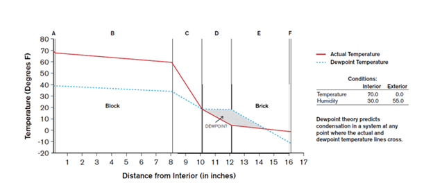
Figure 1 (winter) 8-inch block with rigid insulation
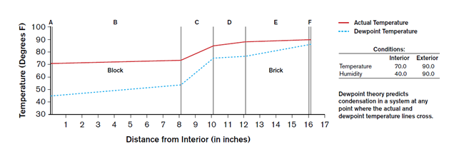
Figure 2 (summer) 8-inch block with rigid insulation
The National Concrete Masonry Association published NCMA TEK 06-17B Condensation Control in Concrete Masonry Walls which includes recommendations for controlling water vapor movement and allowing drying in new residential construction.
The 2009 International Residential Code defines three vapor control classes as follows:
- Class I: <0.1 perms, such as polyethylene sheet, sheet metal or aluminum facing.
- Class II: 0.1 – 1.0 perms, such as kraft faced fiberglass batts, and some vapor control paints.
- Class III: 1.0 – 10 perms, such as some latex or enamel paints.
All Climates
- An air space, such as the properly drained open cores of a single wythe masonry wall or the cavity in a masonry cavity wall, is recommended in all climate zones. The air space provides a drainage plane and allows for better drying.
- Impermeable interior coverings, such as vinyl wallpaper, are not recommended for exterior walls, because their nonbreathable nature tends to trap moisture, inhibit drying and therefore can contribute to mold and mildew within such finishes.
- Interior polyethylene vapor retarders are generally not recommended, because they limit the wall’s ability to dry towards the inside. In some cases, these may be mandated by building codes, particularly in wet climates.
- An additional consideration applies to masonry veneers under certain summer conditions. If masonry is not treated for water repellency, water can be absorbed during heavy rains. Subsequent solar heating evaporates some water, raising the water vapor pressure of air in the wall, and potentially causing condensation. This can be prevented by using surface or integral water repellents to restrict wetting of the masonry, or by applying parging or sheathing paper on the exterior side of the insulation.
Cold and Very Cold Climates
- Air barriers and vapor retarders are installed on the interior side of the insulation in building envelope assemblies when used. This approach allows the wall assembly to dry towards the exterior, as long as vapor-permeable exterior materials are used. For exterior masonry walls, drywall painted with latex paint (Class III) provides a sufficient vapor retarder.
Hot and Humid Climates
- Though there are some exceptions, generally all wall interiors and finishes which are part of an insulated masonry wall assembly may be painted or otherwise finished if desired so long as such finishes and assemblies are breathable and permeable as Code and Standards allow.
- In hot-humid climates the interior space should be dehumidified.
1 Special thanks to Brent Jacobs, Commercial Channel Manager – Michigan DuPont Specialty Products Division, brent.jacobs@dupont.com
Resources:
International Code Council (2018). International Building Code, 2018. International Code Council.
International Code Council (2015). International Building Code, 2015. International Code Council.
National Concrete Masonry Association. (2006). TEK 06-17B, Condensation Control in Concrete Masonry Walls. https://ncma.org/resource/condensation-control-in-concrete-masonry-walls/
Rigid strap anchors are only required at the intersection of participating walls, which comprise part of the lateral force resisting system, when unit interlock or reinforced bond beams are not part of the construction at the intersection (Refer to How should intersecting masonry walls be connected? for more information).
Rigid strap anchors should not be installed where they are not necessary because the projecting portions of the metal strap could pose a safety hazard to persons on the project site if the projecting ends are not protected. Participating walls should be identified specifically as such by notes on the drawings. When required, strap anchors should be provided in accordance with MIM Generic Wall Design Committee Detail 2/S-2 shown below:
Resources:
Society, The Masonry (2016). TMS 402/602 Building Code Requirements and Specification for Masonry Structures, 2016. The Masonry Society.
Society, The Masonry (2013). TMS 402/602 Building Code Requirements and Specification for Masonry Structures, 2013. The Masonry Society.
Wall intersections may be required to meet one of three conditions:
- Transfer of all forces – All forces must be able to be transferred when the intersecting walls are participating walls and are both part of the lateral force resisting system (shear walls).
- Transfer of out-of-plane forces only – When a wall (first wall) is relying upon another wall (second wall) for lateral support, but the first wall is non-participating (not part of the lateral force resisting system), then the intersection must only transfer forces that are acting out-of-plane on the first wall.
- Transfer of no forces – Due to differential support or loading conditions, it may be desirable for no forces to be transferred at a wall intersection.
Transfer of all forces at an intersection, including shear, can be achieved by one of three methods:
- At least 50% of the masonry units at the interface must interlock (overlap),
- Steel anchors of minimum size 1/4-inch x 1.5-inch x 28-inch, including 2-inch long bends at each end, must be grouted into the intersection at a maximum spacing of 48-inches on center, or
- Intersecting reinforced bond beams must cross the intersection at a maximum spacing of 48-inches on center.
A steel anchor detail, which is used to transfer all forces at an intersection in the absence of unit overlap or reinforced intersecting bond beams, is shown in MIM Detail 2/S-2 below (Refer to When are rigid steel connectors (strap anchors) required for anchoring intersecting masonry walls? for more information).
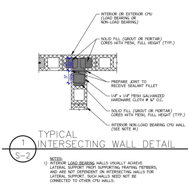
When the wall relies on an intersecting wall for lateral support (transfer out-of-plane forces) only, with no shear (in-plane force) transfer, joint reinforcement or mesh hardware cloth are commonly used. Other metal ties/anchors that provide equivalent connection to joint reinforcement or mesh hardware cloth may be employed. However, TMS 402 currently explicitly permits this type of connection in intersecting walls designed by the Empirical provisions and in intersecting partition walls only.
The 2022 edition of TMS 402 is expected to describe how to anchor partition walls to structural walls so as to provide lateral support only.
- Intersecting walls shall be anchored so as to transfer out-of-plane lateral load from the partition wall to the structural wall.
- Masonry partition walls shall be isolated within their own plane at the intersection, except as required for gravity support of the walls.
- Isolation joints and connectors at the intersections of masonry partition walls and structural walls shall be designed to accommodate the vertical and horizontal deformations of the structural wall.
A mesh hardware cloth detail, which is used to transfer out-of-plane forces only, is shown in MIM Detail 1/S-2 below:
When it is desirable to prevent transfer of all forces at a wall intersection, a movement joint (expansion or contraction) is formed at the intersection. Clay masonry expansion joints are detailed in BIA Technical Note 18A and concrete masonry control joint details are shown in NCMA TEK 10-2C.
Resources:
Society, The Masonry (2016). TMS 402/602 Building Code Requirements and Specification for Masonry Structures, 2016. The Masonry Society.
Society, The Masonry (2013). TMS 402/602 Building Code Requirements and Specification for Masonry Structures, 2013. The Masonry Society.
Joint Reinforcement: Less is More. (July 2015). Masonry Magazine, 44-50.
https://www.masonrymagazine.com/blog/2015/06/24/joint-reinforcement-less-is-more/
Selecting Joint Reinforcement. (June 2014). The Construction Specifier Magazine, 50-58.
https://www.constructionspecifier.com/selecting-joint-reinforcement/
National Concrete Masonry Association. (2019). TEK 10-02D Control Joints for Concrete Masonry Walls-Empirical Method. https://ncma.org/resource/control-joints-for-concrete-masonry-empirical-method/
Brick Industry Association (May 2019). BIA Technical Note 18A Accommodating Expansion of Brickwork
Yes, concrete masonry veneer should include horizontal joint reinforcement placed in mortar bed joints including embedded lap splices of at least 6 inches. Because it is a concrete masonry veneer, the veneer will undergo net irreversible shrinkage due to:
- Wetting and drying cycles
- Carbonation
- A decrease in temperature (reversible)
Because the net effect is shrinkage, a combination of horizontal joint reinforcement and proper placement of control joints1 should be employed to reduce the potential for shrinkage cracking. Note that joint reinforcement should be galvanized or stainless steel and placed with at least 5/8-inch of mortar cover at the weather exposed face and 1/2-inch of mortar cover at the non-weather exposed face. Typically, the industry suggests the horizontal joint reinforcement be placed every 16-inches vertically for 9-gauge wire (W1.7). The horizontal joint reinforcement may be separate and placed in alternate joints or connected to adjustable veneer anchors (seismic clip)2.
Footnotes
- MIM has developed a control joint guide and spreadsheet for determination of control joint spacing available on their website, masonryinfo.local
- The MIM Generic Wall Design Committee has developed veneer details which incorporate these recommendations and are available on their website, masonryinfo.local
Resources
National Concrete Masonry Association. (2001). TEK 10-04 Crack Control for Concrete Brick and other Concrete Masonry Veneers. https://ncma.org/resource/crack-control-for-concrete-brick-and-other-concrete-masonry-veneers/
National Concrete Masonry Association. (2005). TEK 12-02B Joint Reinforcement for Concrete Masonry. https://ncma.org/resource/joint-reinforcement-for-concrete-masonry/
Selecting Joint Reinforcement. (June 2014). The Construction Specifier Magazine, 50-58.
https://www.constructionspecifier.com/selecting-joint-reinforcement/
The TMS 402 permits masonry veneer to be designed by either the alternative engineered method (Refer to TMS 402 Section 12.2.1 for more information) or the prescriptive requirements for anchored masonry veneer (Refer to TMS 402 Section 12.2.2 for more information).
According to the prescriptive requirements, veneer that is backed by wood framing is not required to have shelf angles because the height of such veneer above the support is limited to 30-feet, except that gables are permitted to be 38-feet tall (Refer to TMS 402 Section 12.2.2.6.1 for more information). When the veneer is backed by cold-formed steel framing, the veneer must be supported at each story above 30-feet to the plate or 38-feet to the gable (Refer to TMS 402 Section 12.2.2.7.1 for more information). The veneer height limits for wood-framed and steel-framed backing are permitted to be waived if an engineering analysis is performed in accordance with the alternative engineered method outlined in Section 12.2.1. However, shelf angles are not required for structural support of prescriptively designed masonry veneer backed by concrete masonry unit (CMU) construction, regardless of the veneer height, provided that the veneer is supported on an appropriate foundation.
When the veneer wythe is clay masonry and the backup wythe is CMU, the differential volume change movements (due to clay masonry expansion and CMU shrinkage, as well as thermal movements, creep, etc.) must be considered in the design, regardless of whether the alternative engineered method or prescriptive requirements are used. The taller the wall, the more significant the differential movement. Detailing at penetrations through the wall must be carefully designed and executed. As a practical matter, the height of buildings with such walls should not exceed four stories because it becomes more difficult for detailing (at the top, at ties between wythes and openings) to accommodate the magnitude of differential movement that result from taller structures. Anticipated volume changes can be calculated in accordance with TMS 402 Section 4.2.
When the veneer wythe is the same CMU material as the backup wythe, but the cavity between the wythes is insulated, some differential movement will also occur between wythes, although less than with a veneer wythe of clay masonry. The anticipated differential movement should be calculated so that appropriate details can be developed to accommodate it.
Resources:
Society, The Masonry (2016). TMS 402/602 Building Code Requirements and Specification for Masonry Structures, 2016. The Masonry Society.
Society, The Masonry (2013). TMS 402/602 Building Code Requirements and Specification for Masonry Structures, 2013. The Masonry Society.
Detailing to Accommodate Vertical Expansion. (June 1994). Masonry Construction Magazine, 254-256. https://www.concreteconstruction.net/how-to/construction/detailing-to-accommodate-vertical-expansion_o
Designing for Differential Movement. (April 2005). The Construction Specifier Magazine, 44-56. https://www.masonryinfo.org/wp-content/uploads/2016/05/designing-for-differential-movement-clay-brick-veneer-over-wood-frame.original.pdf
Brick Industry Association. (May 2019). Brick Technical Note 18A Accommodating Expansion of Brickwork
Recessing of masonry courses adds architectural interest to a building façade. However, there are three aspects of recessing that should be considered:
- Recessing creates a “ledge” on the outside face, at the bottom of the recess. Just as with raked and struck mortar joints, this “ledge” increases the risk of water infiltration at the mortar/unit interface. The International Masonry Institute (IMI) recommends installing a mortar wash at this “ledge” at the same time the units are placed on the mortar bed. However, if the recessed course is at or below eye level, this mortar wash will be visible which will impact aesthetics.
- The impact on the cavity behind the veneer, where the recessed course creates a projection into the drainage space. This projection must not decrease the air space behind the veneer to less than the 1-inch minimum required by the TMS 402. Also, consideration should be given to the impact of that projection on the ability of water that has penetrated the veneer and entered the cavity to flow freely downward to the flashing and weep holes. Like the mortar wash on the outside face, IMI recommends a mortar wash on the inside face of the veneer at the top of the recessed course. Unless a cavity is wide enough, however, this mortar wash could be difficult to accomplish and may contribute to mortar droppings in the cavity.
- The reduction of flexural strength, or resistance to cracking. When the veneer consists of solid units (net cross-sectional area of 75% or more per ASTM), which are laid with full mortar bed, the reduction in strength at a slightly recessed course is small and insignificant. However, when hollow units (net cross-sectional area less than 75% per ASTM) are constructed with recessed courses, strength reduction can be significant because these units are typically laid with face shell mortar only and there is little to no face shell overlap at the recessed course. Consequently, hollow units should not be used when recessed courses are desired, unless they are solidly filled with mortar or grout. When the magnitude of the recess equals or exceeds the depth to the core holes in solid units, extra care is required during construction to mitigate the potential for water entry into those core holes.
The magnitude of recessing in veneer is governed by the corbel provisions of TMS 402 Section 5.5. The maximum offset per course must not exceed one-half the nominal unit height nor one-third the nominal unit thickness. If successive courses are each recessed, the total offset should not exceed one-half the veneer wythe thickness. Whether one course or multiple courses are recessed, the back, or inside, surface of the veneer must remain within one-inch of plane.
Resources:
Society, The Masonry (2016). TMS 402/602 Building Code Requirements and Specification for Masonry Structures, 2016. The Masonry Society.
Society, The Masonry (2013). TMS 402/602 Building Code Requirements and Specification for Masonry Structures, 2013. The Masonry Society.
ASTM Standard C216-16, “Standard Specification for Facing Brick (Solid Masonry Units Made from Clay of Shale),” ASTM International, West Conshohocken, PA, 2016, www.astm.org
ASTM Standard C652-17a, “Standard Specification for Hollow Brick (Hollow Masonry Units Made from Clay of Shale),” ASTM International, West Conshohocken, PA, 2017, www.astm.org
ASTM Standard C1634-06, “Standard Specification for Concrete Facing Brick,” ASTM International, West Conshohocken, PA, 2006, www.astm.org
ASTM Standard C55-17, “Standard Specification for Concrete Building Brick,” ASTM International, West Conshohocken, PA, 2017, www.astm.org
ASTM Standard C73-17, “Standard Specification for Calcium Silicate Brick (Sand-Lime Brick),” ASTM International, West Conshohocken, PA, 2017, www.astm.org
ASTM Standard C129-17, “Standard Specification for Nonloadbearing Concrete Masonry Units,” ASTM International, West Conshohocken, PA, 2017, www.astm.org
Details to Avoid. (July 1990). Masonry Construction Magazine, 292-294.
Wall Cavities: Design vs. Construction. (August 2997). Masonry Construction Magazine, 445-446.
Often, clay masonry is incorporated into exterior concrete masonry veneer, or concrete masonry veneer is used in clay brick masonry veneer as accent bands. The bands add architectural interest to the wall and can help hide horizontal elements such as flashing and expansion joints. However, combining these two materials within one wythe of masonry requires special detailing due to the different material properties.
When a band of concrete masonry is located within a clay brick veneer, one method of detailing is to place horizontal joint reinforcement in the mortar joints immediately above and below the band. Also, anchors should be installed within the band whenever the band consists of more than one course. For bands higher than two courses, joint reinforcement should also be placed within the band itself at a spacing of 16-inches on center vertically. Ideally, the joint reinforcement and ties should be placed in alternate joints so that one does not interfere with placement of the other. Some designers, however, prefer placing joint reinforcement in every bed joint in the concrete masonry band. In this case, a tie that accommodates both tie and wire in the same mortar joint should be used, such as a seismic clip wall tie shown below from NCMA TEK 05-02A:
Alternatively, a slip plane can be incorporated into the interfaces between the concrete masonry courses and clay masonry courses to allow unrestrained longitudinal movement between the two materials. This can be accomplished by placing building paper, polyethylene, flashing, or a similar material in the horizontal bed joints above and below the band. When hollow masonry units are used for the band, the slip plane below the band should incorporate flashing so that water draining down the cores of the band can be directed out of the wall at the flashing. When slip planes are used, joint reinforcement should be incorporated into the concrete masonry band in the veneer. The exposed mortar joint at the top and bottom of the band should be raked back and sealed with an appropriate sealant to prevent water penetration at these joints. If the bottom joint incorporates flashing, however, sealant should not be installed to cover the edge of the flashing or the weeps. One detail of a band with slip planes is shown below from NCMA TEK 05-02A:

When slip planes are used, the veneer should be anchored to the backing within 12-inches above and below the isolated band. Also, anchors should be installed within the band whenever the band consists of more than one course. In addition to incorporating joint reinforcement in the concrete masonry, expansion joint spacing should be decreased to reduce the potential for masonry cracking. Experience has shown that vertical expansion joints in the clay masonry veneer should extend through the concrete masonry band, as well, and be placed at a maximum of 20-feet along the length of the wall. Local experience may require reducing the expansion joint spacing from 20-feet to 16-feet. Although concrete masonry construction typically requires control joints rather than expansion joints, control joints should not be used in the concrete masonry band at the expansion joint location.
The recommendations to control differential movement for clay brick masonry bands in a concrete masonry wythe are remarkably similar to those for a concrete masonry band in a clay brick veneer: joint reinforcement above and below the band, wall ties within the band, and wall ties within 12-inches above and below the band. Seismic clip-type wall ties are recommended, as they provide an adjustable wall tie and joint reinforcement in one assembly. With this construction, it is imperative that the concrete masonry veneer control joints not contain mortar where they extend through the clay brick band that would restrict brick expansion.
Cast stone is another material that may be used in feature bands within clay masonry, or vice versa. When the cast stone units are hand held units that are bedded in mortar, banding of cast stone in clay masonry and banding of clay masonry within cast stone masonry should be treated the same as if the cast stone was concrete masonry. When large cast stone units are installed with gravity supported anchors rather than mortar bedding, the cast stone masonry should be isolated from the clay masonry.
Resources:
National Concrete Masonry Association. (2002). TEK 05-02A Clay and Concrete Masonry Banding Details. https://ncma.org/resource/clay-and-concrete-masonry-banding-details/
Brick Industry Association. (May 2019). Brick Technical Note 18A Accommodating Expansion of Brickwork
Cast Stone Institute. (June 2018). Allowing for Movement of Masonry Materials. https://www.caststone.org/bulletins/technical_bulletin_52_allowing-for-movement-of-masonry-

The air space is located directly behind the masonry veneer. This space allows for proper drainage along with flashing and weeps. The principle of a drainage type wall is water that may penetrate from the exterior to the interior through the masonry veneer can flow downward within the air space once the water reaches the inboard surface of the veneer. The amount of water penetrating the masonry veneer will be based on the unit material properties, detailing, and workmanship. For example, one could expect more penetrating water with greater exposure from raked out mortar joints, a sloping roof with no gutters, and head joints that are not full and not compressed. A flashing is installed at the bottom of the air space to collect the water and direct it via the weeps and along the flashing plane to the exterior. According to BIA Technical Note 7; “Properly designed, detailed and constructed drainage wall systems provide excellent water penetration resistance.” According to BIA Technical Note 23A, “Drainage walls are recommended for maximum resistance to rain penetration and minimum efflorescence.” From Masonry Online Construction, “I have heard people recommend using weep vents at the bottom and top of walls to help dry them out following a rain…The faster the walls dry out following rains, the less time available for salts and soluble compounds within the mortar to be carried to the surface…Although vents help dry walls following a rain, those near the top can also allow water to easily enter the walls during rains. Water penetrating the top vents can increase the potential for efflorescence and other moisture related problems. In this case, vents may do more harm than good. There are, however, creative ways of installing vents at the top of walls that protect them from rains…”
The total cavity width would typically include the combined widths of the air space, insulation, and sheathing (depending on the backup).
Footnotes
- The TMS 402/602-22 is still being developed and, as such, these numbers have not been finally adopted and codified.
Resources
Society, The Masonry (2016). TMS 402/602 Building Code Requirements and Specification for Masonry Structures, 2016. The Masonry Society.
Society, The Masonry (2013). TMS 402/602 Building Code Requirements and Specification for Masonry Structures, 2013. The Masonry Society.
Brick Industry Association. (November 2017). BIA Technical Note 7 Water Penetration Resistance – Design and Detailing
Brick Industry Association. (June 2019). BIA Technical Note 23A Efflorescence – Causes and Prevention
Most of the brick in walls designed and constructed today are classified as a veneer. A veneer is a masonry wythe that provides the exterior finish of a wall system that transfers our-of-plane load directly to a backing. A veneer is an element that is not considered to add strength or stiffness to the wall assembly. This FAQ will address the brick anchor embedment for anchored veneer. Anchored veneer is secured to and supported laterally by the backing through anchors and supported vertically by the foundation or other structural elements.
Article 3.4E of the TMS 602 addresses veneer anchors (corrugated sheet-metal anchors, sheet metal anchors, and wire anchors) for solid units and hollow units. A solid masonry unit is defined as having a net cross-sectional area of 75 percent or more of its gross cross-sectional area. A hollow masonry unit is defined as having a net cross-sectional area of less than 75 percent of its gross cross-sectional area.
For solid units, anchors are required to be embedded in mortar a minimum of 1-1/2-inch with at least 5/8-inch mortar cover to the outside face.
For hollow units, anchors are required to be embedded in mortar or grout a minimum of 1-1/2-inch with at least 5/8-inch mortar or grout cover to the outside face. Proper anchorage of veneer anchors into hollow units can be achieved by:
- Mortaring anchors in bed joints or on the cross-webs of the units
- Grouting the cells or cores adjacent to the anchor
- Following the anchor manufacturer’s requirements for installing the anchor into the cell or core above or below the bed joint and filling the cell or core containing the anchor with mortar or grout
Resources:
Society, The Masonry (2016). TMS 402/602 Building Code Requirements and Specification for Masonry Structures, 2016. The Masonry Society.
Society, The Masonry (2013). TMS 402/602 Building Code Requirements and Specification for Masonry Structures, 2013. The Masonry Society.
Chapter 12 of the TMS 402 Building Code Requirements for Masonry Structures contains provisions relating to the design of veneers. The Code Commentary to Section 12.2.2.10.3, Seismic Design Categories E and F, states; “The 1995 through 2011 editions of the MSJC Code required that masonry veneer in Seismic Design Categories E and F be provided with joint reinforcement, mechanically attached to anchors with clips or hooks. Shaking table research (Klinger et al, 2010(b)) has shown that the requirement is not necessary or useful so the requirement was removed in the 2013 edition of the MSJC Code.”
Resources:
Society, The Masonry (2016). TMS 402/602 Building Code Requirements and Specification for Masonry Structures, 2016. The Masonry Society.
Society, The Masonry (2013). TMS 402/602 Building Code Requirements and Specification for Masonry Structures, 2013. The Masonry Society.