Updated: February 2015
This Bulletin serves to caution against using exposed metal drip edges at all locations within pedestrian reach. Reachable locations, typically, include base of wall, first floor window sills, garden walls and site walls. Exposed metal and metal drip edges, including laps and corners, could result in unforeseen injuries due to sharp edges. Even those with hemmed edges can be dangerous at laps and outside corners when they are within reach. Durable, fully adhered flexible membrane flashing, is recommended at these locations. Extreme caution should be taken with exposed metal flashings.
The use of exposed drip edges becomes more important with wall height. By definition, drip edges serve to deflect downward cascading moisture away from the masonry substrate and other building components below. Since there is little to no substrate below the base flashing course and little below first floor window sills or garden walls, no metal drip edge is necessary. At these locations a fully adhered flexible flashing membrane will serve well to divert drainage cavity moisture to the exterior, and furthermore, will prevent exterior moisture from entering under the membrane.
The Masonry Institute of Michigan further recommends that all flashing be capable of withstanding harsh all-weather conditions including wind, ultraviolet degradation and extreme temperature cycles. This applies to all necessary locations, including but not limited to base of wall, sills, above window, door and mechanical openings, relief angles, high walls at low roofs and at copings.
All exposed metal flashing requires hemmed edges with laps sealed with non-skinning butyl sealant and a continuous compatible caulk sealant between the underside of the sloped hemmed drip edge and the substrate below. A continuous bead of sealant under the drip edge further prevents exterior moisture from entering beneath the metal drip edge at locations that include but are not limited to above window, door and mechanical openings, relief angles and top of wall copings.
Originally posted: February 2006
Date: July 2021
Please use this Bulletin as a guide when editing or reviewing project masonry specifications, specifically for mortar selection. MIM recommendations are provided in bold typeface for convenience. A quick summary is provided at the end of the bulletin.
Mortar Specifications
Modern mortars are typically covered under ASTM C270 Standard Specification for Mortar for Unit Masonry. ASTM C270 provides two methods for specifying mortars: the proportion specification and the property specification. If neither of these are specified, the proportion specification (default) shall govern under ASTM C270.
Although it will govern if neither is specified, MIM recommends specifying the proportion specification for mortars used in masonry construction.
Mortar Types
Modern types of cement mortars include types M, S, N, and O. Table X1.1 Guide for the Selection of Masonry Mortars is included in ASTM C270 Appendix and copied below:
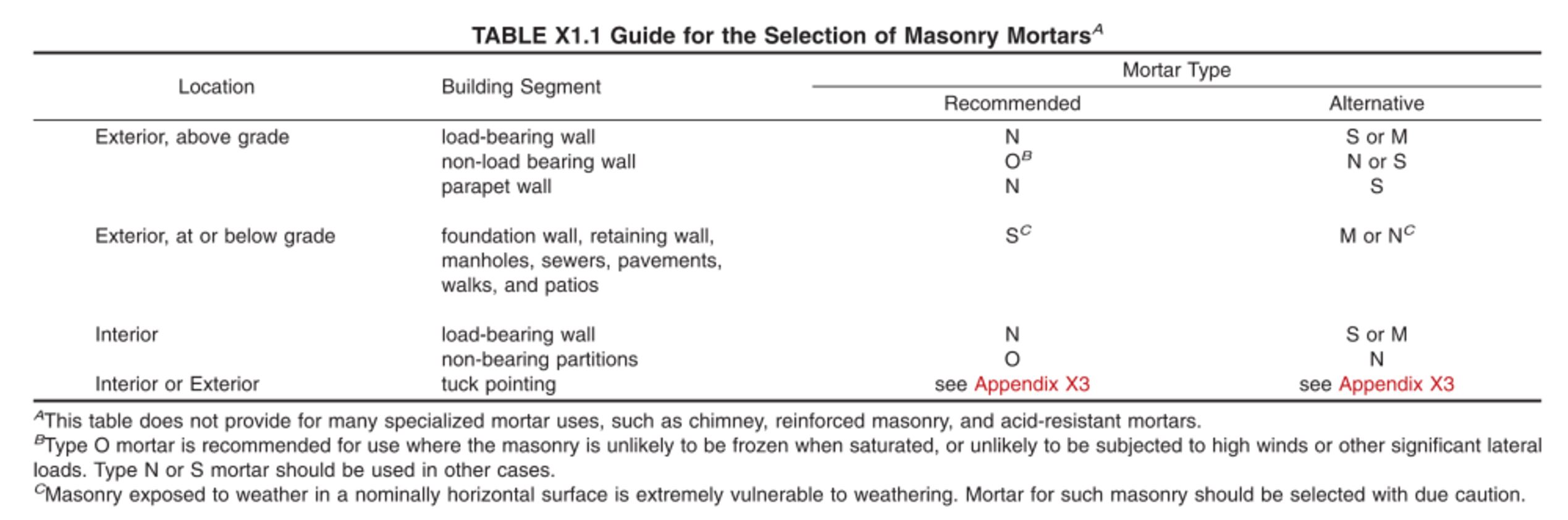
BIA Technical Note 8B Mortars for Brickwork – Selection and Quality Assurance also includes recommendations for mortar types. As stated in the technical note, each mortar type has some basic characteristics:
- Type N mortar: general all-purpose mortar with good bonding capabilities and workability
- Type S mortar: general all-purpose mortar with higher compressive and flexural bond strength
- Type M mortar: high compressive-strength mortar but not very workable
- Type O mortar: low-strength mortar used mostly for interior applications and restoration. As noted in Footnote B, Type O is recommended when masonry is unlikely to be frozen or saturated, or subjected to high winds or other significant loads.
For the purposes of this bulletin, MIM has broken down masonry construction by the intended usage of the masonry below, with a discussion on recommended mortar types.
Load-Bearing Concrete Masonry Units (CMUs), above grade
For exterior or interior load-bearing masonry wall assemblies, ASTM C270 recommends Type N mortar with an alternative of Type S or M.
Type N mortar typically has less compressive strength than Types S or M. For comparison purposes, the average 28-day compressive strength of Type N mortar required by the property specification is 750 psi compared to 1800 psi and 2500 psi for Types S and M, respectively. Type N mortars are also typically easier to clean from the surface of a wall assembly when compared to Types S or M.
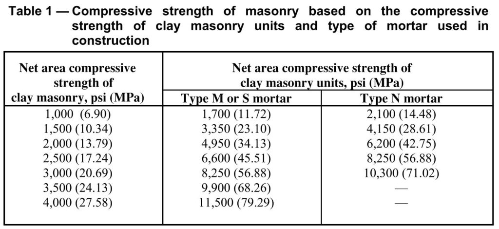
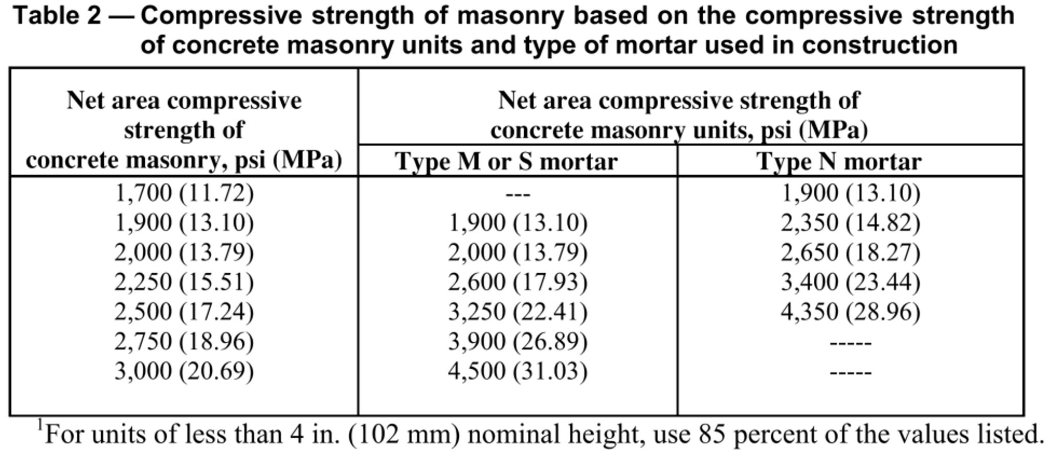
For structural design, the engineer of record must establish a baseline minimum net area compressive strength of clay or concrete masonry (f’m) to be used in design. The f’m value is dependent on mortar type as shown in Table 1 and Table 2 of the TMS 602 Specification for Masonry Structures and Commentary:
MIM recommends specifying the weakest mortar type that will satisfy structural requirements. For the purposes of load-bearing CMUs used above grade, MIM recommends using either Type N or Type S mortar for both interior and exterior uses.
Example: If the engineer is using 2,000 psi as their f’m in their basis of design, a Type N mortar could be used if the average unit compressive strength of the CMU was 2,650 psi. Type S mortar could be used if the average unit strength of the CMU was 2,000 psi. CMU compressive strength is tested and measured in accordance with ASTM C140 Standard Test Methods for Sampling and Testing Concrete Masonry Units and Related Units. The minimum net area compressive strength of CMU is specified as 2,000 psi for the average of 3 units in ASTM C90 Standard Specification for Loadbearing CMUs.
Non-Load Bearing CMUs, above grade (not including veneers)
For exterior or interior non-load bearing masonry wall assemblies, ASTM C270 recommends Type O mortar (subject to Footnote B above) with an alternative of Type N or S.
Note: Although an exterior or interior wall may be non-load bearing, it may still be subject to lateral forces both in-plane and out-of-plane. MIM recommends that non-loadbearing exterior walls are treated the same as load-bearing walls, (i.e. as structural).
As discussed above, Type N mortar is typically easier to clean from the surface of a wall assembly when compared to Types S or M.
For structural design, interior walls are subject to minimum lateral loads required under the International Building Code, and the engineer will be required to select an appropriate f’m. Additionally, depending on the Seismic Design Category, unreinforced and ungrouted masonry may be used for interior partition walls. The flexural tension in this case will be resisted by the masonry and the bond strength of the mortar will be critical to the wall performance.
MIM recommends specifying the weakest mortar type that will satisfy structural requirements. For the purposes of non-load bearing CMUs used above grade, MIM recommends using either Type N or Type S mortar for both interior and exterior uses.
Example: An interior partition wall spans vertically 12’-0” from the floor to the deck and is subject to the 5 psf minimum horizontal load required under Section 1607.14 of the International Building Code. Based on a flexural analysis, the wall can be unreinforced and ungrouted (See MIM Unreinforced Wall Guide). Type N mortar would be appropriate.
CMU and Brick Anchored Veneers
For exterior non-load bearing masonry wall assemblies, specifically veneers, ASTM C270 recommends Type O mortar (subject to Footnote B above) with an alternative of Type N or S.
BIA Technical Note 8B Mortars for Brickwork – Selection and Quality Assurance also includes a simplistic mortar selection as follows:
- Type N for normal brickwork applications
- Type S for stronger brickwork applications
Based on the intended use, BIA provides Table 1 below with more explicit guidance on mortar selection:
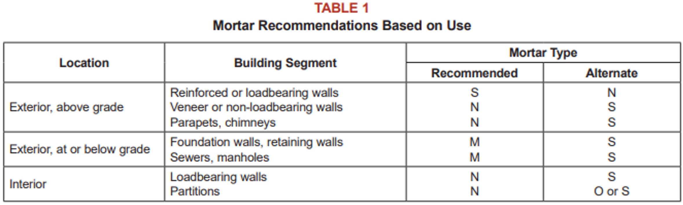
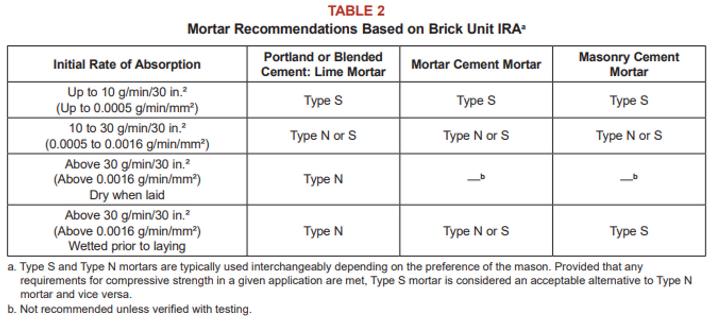
As stated by BIA, the bond between brick and mortar is the most important property to consider when selecting mortar type. Based on this, BIA provides recommendations for mortar type based on the initial rate of absorption (IRA) which can affect bond. These recommendations are provided by BIA in Table 2 below:
NCMA publishes TEK 03-06C Concrete Masonry Veneers and TEK 09-01A Mortars for Concrete Masonry which provide some guidance on mortar selection.
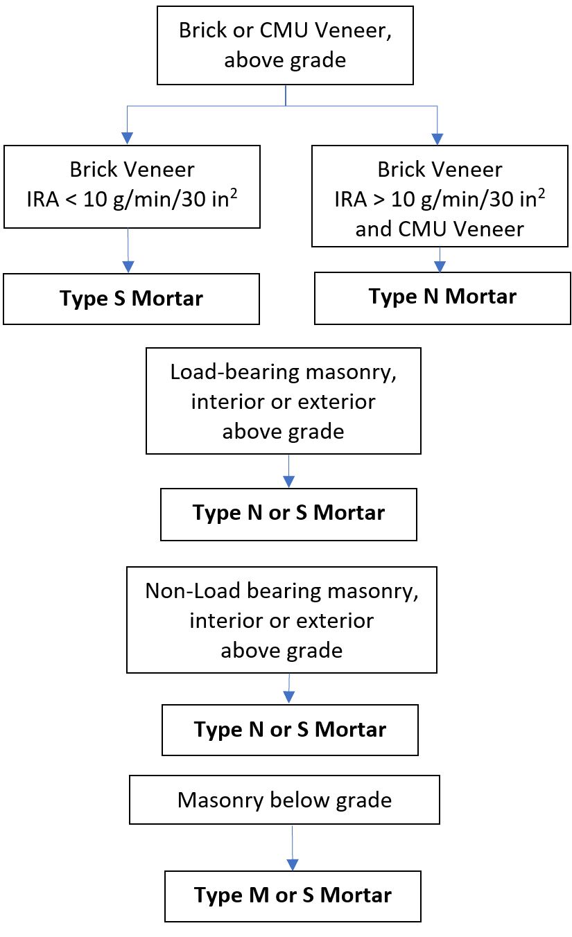
MIM recommends specifying the weakest mortar type that will satisfy structural requirements. For the purposes of CMU and brick anchored veneers used above grade, MIM recommends using Type N mortar unless the IRA requires a higher strength mortar. CMU veneers do not have an IRA test, and thus Type N mortar is recommended for this material.
Load-Bearing and Non-Load Bearing Masonry, below grade
For exterior masonry wall assemblies, ASTM C270 recommends Type S mortar (subject to Footnote C above) with an alternative of Type M or N. As noted in ASTM C270, masonry exposed to weather in a nominally horizontal surface is extremely vulnerable to weathering. Mortar for such masonry should be selected with due caution.
For the purposes of masonry used below grade, MIM recommends using Type M or S mortar.
Cement Types
Modern cements used in masonry construction include:
- Cement-lime mortars (ASTM C150 Standard Specification for Portland Cement) (ASTM C207 Standard Specification for Hydrated Lime for Masonry Purposes)
- Masonry cement mortars (ASTM C91 Standard Specification for Masonry Cement)
- Mortar cement mortars (ASTM C1329 Standard Specification for Mortar Cement)
As noted by BIA, because of the strict controls on air content and the minimum strength requirement, mortar cement and Portland cement-lime mortars are treated similarly in the TMS 402 Building Code Requirements for Masonry Structures. The only mortar cement that contains a minimum bond requirement is mortar cement mortar.
The cement type is limited in Seismic Design Categories D, E, and F. As stated in Section 7.4.4.2.2 of the TMS 402 Building Code Requirements for Masonry Structures, fully grouted participating elements shall be designed and specified with Type S or Type M cement-lime mortar, masonry cement mortar, or mortar cement mortar. Partially grouted participating elements shall be designed and specified with Type S or M cement-lime mortar or mortar cement mortar.
MIM recommends specifying the cement type that produces the most workable mortar that is the most common in the project area. For Seismic Design Categories D, E, and F cement-lime or mortar cement mortars are required for partially grouted walls; and cement-lime, mortar cement, and masonry cement mortars are permitted for fully grouted walls.
Summary
This summary is provided based on the Michigan markets and for our Seismic Design Category (SDC), A or B. This summary may not be appropriate for other areas of the U.S. Additionally, structural requirements may require use of a higher strength mortar based on the discussion above. MIM recommends specifying the weakest mortar type that will satisfy structural requirements.
Given the SDCs in Michigan calculated in accordance with ASCE 7 Minimum Design Loads for Buildings and Other Structures, MIM recommends that the specifier allow the mason contractor to select the cement type for use in the mortar. Cement-lime mortars, mortar cement mortars, and masonry cement mortars are all permitted in our SDCs for ungrouted, partially grouted, and fully grouted wall assemblies. As such, the mason is the best judge for what cement type will work best on a given project in the Michigan markets.
References
BIA Technical Note 8B Mortars for Brickwork – Selection and Quality Assurance
NCMA TEK Note 03-06C Concrete Masonry Veneers
TEK 09-01A Mortars for Concrete Masonry
TMS 402/602-13 Building Code Requirements and Specification for Masonry Structures
International Building Code (2015)
NOVEMBER 2012: This Bulletin serves to remind whoever is placing the order for concrete masonry units to first review the contract documents (drawings and specifications) to see what the designer (typically, the structural engineer) has specified for f’m and mortar type.
For years, designers have been specifying an f’m equal to 1500 psi with Type S mortar using the unit strength method. According to the Code this would require a block compressive strength of 1900 psi.
Recently on projects, some designers are now specifying a higher f’m, i.e., 2000 psi, 2500 psi and 3000 psi with Type S mortar. According to the Code this would require a block compressive strength of 2800 psi, 3750 psi and 4800 psi, respectively.
Some of the benefits for specifying the increased strength are less grout required for partially grouted walls, less reinforcement required for walls, and reinforcement lap lengths reduced. In fact, a recent article in the Masonry Edge/the Story Pole, Vol. 7, No. 1,
Embodied Energy of Concrete Masonry , David Biggs, PE, SE, Dist M ASCE, HTMS, pages 12-15, states; “In each case, upgrading f’m from 1500 psi to 2000 psi reduces the amount of grout and reinforcement by 50% for partially grouted walls…”
Date: January 2015
Please use this Bulletin as a guide when specifying concrete masonry units (CMUs).
Typically Concrete Product Producers manufacture their CMU’s out of locally available aggregates. These aggregates when mixed with cement and water produce the specific block physical properties inherent to the locally available aggregates.
When it comes to block making, the State of Michigan is abundant with normal weight aggregates of sand, gravel, and limestone (ASTM C-33) throughout the state, which when utilized in the concrete block manufacturing process will result in concrete masonry units (CMU’s) that ASTM classifies as normal weight (density of 125 lbs/cf and above).
For many years, expanded slag, a lightweight aggregate (ASTM C-331) has been available in the southeast Michigan area, which offered CMU manufacturers the option of blending the expanded slag with normal-weight aggregates to produce a medium-weight CMU (density of 105 lbs/cf to less than 125 lbs/cf). Compared to normal-weight units, these medium-weight units offered the mason contractor a lighter weight unit, and offered the designer potentially increased fire ratings and reduced coefficients of thermal expansion, all for a reasonably priced premium compared to normal-weight units.
Over the years, some Michigan manufacturers chose to inventory only normal-weight units, some have inventoried both normal-weight and medium-weight units, and some have chosen to inventory only medium-weight units. Typically, at least in southeast Michigan, a medium-weight unit came to be known as the “standard” unit that is inventoried in most block yards.
Recently, however, expanded slag has become virtually unavailable to southeast Michigan producers, unless trucking the aggregate in from neighboring states or even Ontario. The premium for a medium-weight block compared to normal-weight has increased approximately four times from what is was just a year ago, a premium that most manufacturers feel the market will not bear. As a result, many manufacturers have either changed or are in the process of changing their everyday inventory over to normal-weight units. Medium-weight units will still be available in the Michigan market, but on a much more limited basis than in the past and also at the higher cost premium.
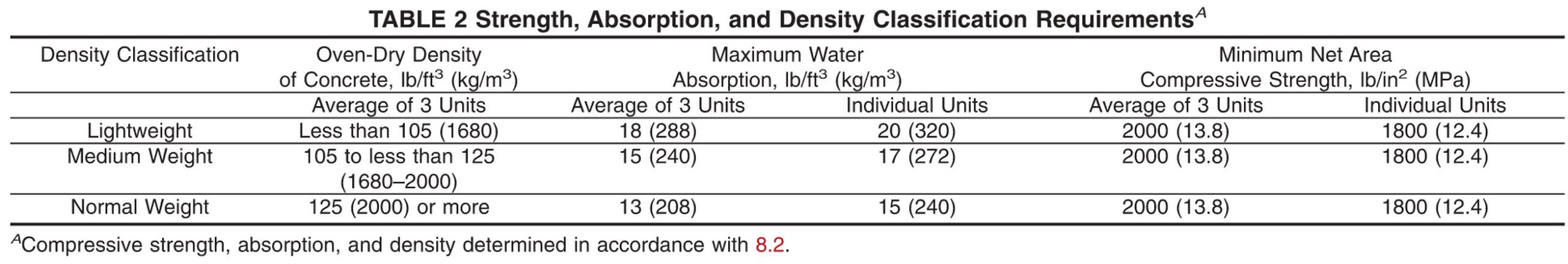
To assist the designer and specifier, the following are suggested guidelines. CMUs should be specified to meet ASTM C90, the Standard Specification for Loadbearing Concrete Masonry Units. There are three density classifications for CMUs: 1) normal weight (125 pcf or more), 2) medium weight (105 pcf to less than 125 pcf) and 3) lightweight (less than 105 pcf).
- All three density classifications have to meet a minimum net area compressive strength of 1900 psi. Depending on the mortar type, the compressive strength of the wall increases with higher density CMUs.
- Based on the calculation procedure, the sound transmission class (STC) increases with higher density walls. Code, typically, requires STCs of not less than 50.
- When designing for moisture management and mitigation in single wythe CMU walls, three levels of defense should be considered: surface protection (properly constructed mortar joints, surface water repellents, surface coatings), internal protection (integral water repellents), and drainage/drying (flashing, weeps, vents).
- The coefficients of thermal expansion of CMUs depend to some degree on density and on the type of aggregate used. Normal weight units have an expansion coefficient of about 5 x 10⁻⁶/F and the value for lightweight units is about 4 x 10⁻⁶/F. The TMS 402-11 Building Code Requirements for Masonry Structures shows 4.5 x 10⁻⁶/F.
- As the density of the unit increases, the unit’s weight increases.
- In general, fire resistance ratings with lower density walls provide more fire resistance.
- Thermal resistance with lower density walls provide higher R-values.
- The heat capacity (thermal mass) increases with higher density walls.
Note, when particular features are desired such as higher compressive strength, fire resistance, thermal performance or acoustical performance, these features should be specified separately. Your local block manufacturer should be consulted as to the availability of CMUs having the desired features. If you have any questions regarding this Bulletin and/or block specifications, please feel free to contact the Masonry Institute of Michigan at phil@masonryinfo.org.
Date: April 2015
In the last several years, considerable attention has been given to energy lost through the building envelope. In response to increasingly demanding energy code requirements, professionals are now incorporating control layers (water, air, thermal and vapor), whenever possible, in their masonry wall designs. Spray polyurethane foam (SPF) insulation is somewhat unique in that manufacturers of this product claim that it can provide all four control layers in one application. For that reason, there has been interest in using SPF.
The Generic Wall Design Committee (GWDC) operates under the auspices of the Masonry Institute of Michigan (MIM). As a complement to the sets of details that address masonry cavity walls with rigid insulation and mineral wool insulation, GWDC began developing a set of masonry cavity wall details utilizing SPF insulation. However, this effort was suspended in 2013, when a paper that revealed some concerns with SPF came to the attention of the MIM. The paper was titled, Dimensional Stability Considerations in Spray Polyurethane Foam Air Barriers, and was presented at an ASTM Symposium on Building Walls Subject to Water Intrusion and Accumulation: Lessons from the Past and Recommendations for the Future, after which it was published in ASTM STP 1549.
The following considerations were presented in the referenced paper:
SPF undergoes short and long term shrinkage, which must be considered in the design and detailing.
The potential for shrinkage and curling must be considered where the foam interfaces with other wall and roof system components (i.e., flashing membranes, transition membranes, closures, terminations, air barriers, water barriers and other accessory materials).
Because SPF is site-mixed, its physical properties can vary. Factors that affect the physical properties of SPF include mixture proportions, thicknesses, ambient and substrate temperatures, moisture or humidity conditions, as well as other factors.
Additional concerns that have come to the attention of MIM include:
Required protection of other building components, pedestrians, vehicles, and landscaping in the vicinity where SPF is being applied is more extensive than with other products.
Guides for how to repair out-of-compliance SPF are not available.
Guidance for design, detailing, and application of SPF to address the considerations and concerns raised have not been developed by the spray foam industry. Until the time when such guidance is available, the GWDC masonry cavity wall details that incorporate SPF will not be finalized nor published by MIM.
If you have any questions regarding this Bulletin, please feel free to contact the Masonry Institute of Michigan at phil@masonryinfo.org.
MASONRY SPECIFICATIONS: UNDERSTANDING TOLERANCES
TMS 602 Specification vs. MasterSpec
Date: May 2021
Please use this Bulletin as a guide when editing or reviewing project masonry specifications.
Typically, the Architect/Engineer (“Designer”) will use a product selection tool (e.g., MasterSpec or BSD SpecLink) to develop the material specifications for a project. The product selection tool will commonly be based on the legally adopted building code and referenced standards. Most specifications are divided into three parts: Part 1 – General, Part 2 – Products, Part 3 – Execution.
Masonry tolerances are included in Part 3 – Execution. The Michigan Building Code adopts the Building Code Requirements and Specification for Masonry Structures (TMS 402/602) as the referenced standard for masonry construction. The code tolerances and MIM’s recommendation are presented below, along with a discussion.
Code Tolerances & MIM Recommendation
MIM recommends using the tolerances provided in the TMS 602 Specification for Masonry Structures. The Designer is encouraged to refer to the TMS 602 in the project specification rather than provide values for tolerances unless specifically required. The TMS 602 requirements are intended to ensure the structural performance of unit masonry. If more stringent tolerances are included in the project specification, there may be cost implications since ASTM tolerances for masonry units may require cutting of the units for increased precision. More stringent tolerances require the use of units with tighter dimensional tolerances than typical masonry units. Tighter tolerances do not necessarily improve the strength, durability, or the resistance of brick to water penetration. If tighter tolerances are required, then more precise units (if available) need to be specified (or cut) along with their allowed dimensional variations. MIM encourages all parties to agree on tolerances at the pre-construction meeting.
TMS 402/602-13
Masonry erection is presented in Article 3.3 of the TMS 602. Specifically, site tolerances are presented in Article 3.3 F, as follows:
- Dimension of elements
- In cross section of elevation . . . . . . . . . . . . . . . . . . . . . . -1/4 in., +1/2 in.
- Mortar joint thickness
- Bed joint between masonry courses . . . . . . . . . . +/-1/8 in.
- Bed joint between flashing and masonry . . . . . -1/2 in., +1/8 in.
- Head joint . . . . . . . . . . . . . . . . . . . . . . . . . . . . . . . . . . . . . -1/4 in., +3/8 in.
- Collar joint . . . . . . . . . . . . . . . . . . . . . . . . . . . . . . . . . . . . -1/4 in., +3/8 in.
- Grout space or cavity width, except for masonry walls passing framed construction . . . . . . . . -1/4 in., +3/8 in.
- Elements
- Variation from level:
- Bed joints . . . . . . . . . . . . . . . . . . . . . . . . . . . . . . . . . . . . . . . . . . . .+/-1/4 in. in 10 ft., +/-1/2 in. maximum
- Top surface of load-bearing walls . . . . . . . . . . . . . . . . . . . . . +/-1/4 in. in 10 ft., +/- 1/2 in. maximum
- Variation from plumb . . . . . . . . . . . . . . . . . . . . . . . . . . . . . . . . . . . . .+/- 1/4 in. in 10 ft., +/- 3/8 in. in 20 ft., +/- 1/2 in. maximum
- True to a line . . . . . . . . . . . . . . . . . . . . . . . . . . . . . . . . . . . . . . . . . . . . . +/- 1/4 in. in 10 ft., +/- 3/8 in. in 20 ft., +/- 1/2 in. maximum
- Alignment of columns and walls (bottom versus top) . . . . +/- 1/2 in. for loadbearing walls and columns, +/- 3/4 in. for non-loadbearing walls
- Variation from level:
- Location of elements
- Indicated in plan . . . . . . . . . . . . . . . . . . . . . . . . . . . . . . . . . . . . . . . . . +/- 1/2 in. in 20 ft., +/- 3/4 in. maximum
- Indicated in elevation . . . . . . . . . . . . . . . . . . . . . . . . . . . . . . . . . . . . +/- 1/4 in. in 20 ft., +/- 3/4 in. maximum
MasterSpec
Masonry tolerances are presented in Section 3.03 Tolerances. The language from MasterSpec is copied below for reference. For discussion, the underlined text is not included and more stringent than required by the TMS 602.
- Dimensions and Locations of Elements:
- For dimensions in cross section or elevation, do not vary by more than plus 1/2 inch (12 mm) or minus 1/4 inch (6 mm).
- For location of elements in plan, do not vary from that indicated by more than plus or minus 1/2 inch (12 mm).
- For location of elements in elevation, do not vary from that indicated by more than plus or minus 1/4 inch (6 mm) in a story height or 1/2 inch (12 mm) total.
- Lines and Levels:
- For bed joints and top surfaces of bearing walls, do not vary from level by more than 1/4 inch in 10 feet (6 mm in 3 m), or 1/2-inch (12-mm)
- For conspicuous horizontal lines, such as lintels, sills, parapets, and reveals, do not vary from level by more than 1/8 inch in 10 feet (3 mm in 3 m), 1/4 inch in 20 feet (6 mm in 6 m), or 1/2-inch (12-mm)
- For vertical lines and surfaces do not vary from plumb by more than 1/4 inch in 10 feet (6 mm in 3 m), 3/8 inch in 20 feet (9 mm in 6 m), or 1/2-inch (12-mm)
- For conspicuous vertical lines, such as external corners, door jambs, reveals, and expansion and control joints, do not vary from plumb by more than 1/8 inch in 10 feet (3 mm in 3 m), 1/4 inch in 20 feet (6 mm in 6 m), or 1/2-inch (12-mm)
- For lines and surfaces, do not vary from straight by more than 1/4 inch in 10 feet (6 mm in 3 m), 3/8 inch in 20 feet (9 mm in 6 m), or 1/2-inch (12-mm)
- For vertical alignment of exposed head joints, do not vary from plumb by more than 1/4 inch in 10 feet (6 mm in 3 m), or 1/2-inch (12-mm)
- For faces of adjacent exposed masonry units, do not vary from flush alignment by more than 1/16 inch (1.5 mm).
- Joints:
- For bed joints, do not vary from thickness indicated by more than plus or minus 1/8 inch (3 mm), with a maximum thickness limited to 1/2 inch (12 mm).
- For exposed bed joints, do not vary from bed-joint thickness of adjacent courses by more than 1/8 inch (3 mm).
- For head and collar joints, do not vary from thickness indicated by more than plus 3/8 inch (9 mm) or minus 1/4 inch (6 mm).
- For exposed head joints, do not vary from thickness indicated by more than plus or minus 1/8 inch (3 mm).
BSD SpecLink
Masonry tolerances are presented in Section 3.17 Tolerances. The language from BSD SpecLink is copied below for reference. For discussion, the underlined text is not included and more stringent than required by the TMS 602.
- Install masonry within the site tolerances found in TMS 402/602.
- Maximum Variation from Alignment of <<Columns; Pilasters; and [___________]>>: <<1/4 inch (6mm); or [____] inch (__ mm)>>.
- Maximum Variation from Unit to Adjacent Unit: <<1/16 inch (1.6 mm) or [____] inch ([____] mm)>>.
- Maximum Variation from Plane of Wall: 1/4 inch in 10 ft (6 mm/3 m) and 1/2 inch in 20 ft (13 mm/6m) or more.
- Maximum Variation from Plumb: 1/4 inch (6 mm) per story non-cumulative; 1/2 inch (13 mm) in two stories or more.
- Maximum Variation from Level Coursing: 1/8 inch in 3 ft (3 mm/m) and 1/4 inch in 10 ft (6 mm/3m); 1/2 inch in 30 ft (13 mm/9 m).
- Maximum Variation of Mortar Joint Thickness: Head joint, <<minus 1/4 inch, plus 3/8 inch (minus 6.4 mm, plus 9.5 mm); or minus [___] inch, plus [___] inch (minus [___] mm, plus [___] mm)>>
- Maximum Variation from Cross Sectional thickness of Wall: <<1/4 inch (6 mm); or [___] inch (___ mm)>>.
Discussion
TMS 602 provides tolerances for masonry construction. Additionally, there are permissible variations in dimensions of manufactured masonry units provided in ASTM standards. For instance, ASTM C90 (Standard Specification for Loadbearing Concrete Masonry Units) states that, “For standard units, no overall dimension (width, height, and length) shall differ by more than +/- 1/8 in. (3.2 mm) from the specified dimension. ASTM C216 (Standard Specification for Facing Brick) includes Table 2 Tolerances on Dimensions. For example, for a specified dimension of 3-4 in., Type FBX units are permitted to vary by 3/32 in. and Type FBS units are permitted to vary by 1/8 in.
Given the permitted tolerances of masonry units and the manufacturing process, in many cases it may be impractical and uneconomical to satisfy the tolerances included in MasterSpec or BSD SpecLink. For instance, if a single wythe loadbearing CMU wall is to be constructed MasterSpec would require faces of adjacent exposed masonry units to not vary from flush alignment by more than 1/16 in. and BSD SpecLink would require the maximum variation from unit to adjacent unit to be 1/16 in. These tolerances are not specified in TMS 602, and the CMU units are permitted by ASTM C90 to vary by +/- 1/8 in. To satisfy the more stringent tolerance requirements, the contractor or producer may be required to cut the units so that the specified dimensions are more precise. This will add cost to a project to satisfy these stringent dimensions. Therefore, unless extreme circumstances dictate, MIM recommends using the tolerances provided in TMS 602.